
21.08.2017
Today we met for the first time again after the summer holidays. We reviewed the project in our group and decided what we wanted to do to expand or change.
28.08.2017
Renewed communication of the group members about possibilities of the project. Final fixing for the creation of the maintenance booklet. I also started
For the first time detailed the system and make me the Fanuc
Start up the robot.
This is a different way to delete a reset. It's bloody any of the errors:
SRVO-062 BZAL alarm (group: 1 axis: 1-5)
This pleased that battery alarm output, the buffer batteries of the measuring systems. To make sure that I have found the right batteries. I reported to our project supervisor Mr. Musielack that
we have batteries and the type of battery on. Since I do not continue now
I started with Fabian the creation of the maintenance booklet.
04.09.2017
Today we continued the preparation and processing of the specifications, always in communication with our other team members.
We also started adding more parts needed for the plant, from the Phoenix
Pick out online catalog.
Furthermore, we selected one of Thomas designed logos for our System.
11.09.2017
Appraisal of the plant with Mr. Wohlfahrt from the company SEW. He answers questions about the drives regarding the positioning of the conveyor belt and the magazine drive.
He assured us, components for a reorganization of the magazine sponsors. We should have a position transmitter, connection cable and an associated frequency
converter
to get. With these components we will be able to position the magazine.
In addition, I removed the old backup batteries from the robot because the new ones were there.
Completing the Excel order list for the Phoenix Online Shop, I had to raussuchen the prices in the online shop.
Furthermore, we completed today the specification.
18.09.2017
At work, I removed the solder tags on the old backup batteries and soldered the new batteries. I now install the backup batteries in the robot. The battery change alarm
Now I started the operation of the robot in collaboration with Fabian Rudersdorf. Calibration of the axes according to the instructions in the manual. The axes must go to the arrow marks. The robot has been mastered, he now whistled again where his zero points are and where he stands.
Running an old program to get a problem for the robot.
25.09.2017
Reading into the manual of the robot,
-Menu cards (chapter 1.4)
-Knowledge of the Robot Coordinate Systems (Chapter 2.1.1)
-How will a program be written (Chapter 5)
Create a program called "Flamizza" Teaching different positions and moving off positions.
In addition,
I made acquaintance with the existing outputs of the robot, which included: gripper (open / close), oven door (open / close).
16.10.2017
Today I have the program from
last time deleted, because it only served to understand how to am
Robot teaches positions.
For practice, I have created a new program: FLAMIZZA (Comment:
Flamizza 4.0), this will now be used for our facility.
In this program I have approached and taught positions, these positions are to be a skeleton for the later sequence of the robot and have to be re-taught to correct later, especially
because the robot gets a new gripper.
Programming:


Teach robot program positions:


23.10.2017
Create a graphet for the attachment
Parts of the Grafcet:
- Emergency stop + basic structure
- Expiry magazine
- Drain conveyor
Conversation with Mr. Wohlfahrt the
Company SEW, topic of the conversation was to optimize the magazine of the plant. Sir
Wohlfahrt was of the opinion that the currently installed engine, an asynchronous motor,
can be used further. He suggested that we SEW one
Positioners get to enable the positioning of the magazine.
Besides, we realized that the existing frequency converter was not for that
it is suitable to receive encoder signals. For this we should have a new one
Get frequency converter that has this option.
06.11.2017
Completion of the Grafcets
Parts of the Grafcet:
- Conveyor belt: selection pizza
- Conveyor belt: Selection Flammkuchen
- Drain robot
The order from Phoenix Contact
arrived today. I have Fabian Rudersdorf my commissioning of the WLAN
Module supported. Since the device has switched off WLAN at the factory, it had to
be activated by us. This had to be connected to the module via LAN
be accessed. Problems here were setting the interface on
Laptop. After the connection was established, the module could be commissioned
and Wi-Fi enabled.
13.11.2017
Today we got the still missing components of the company SEW, which included a position sensor with connecting cable and a frequency
converter. For the frequency converter, we also got a donor card, I had this with a on the
Frequency converter available Replace module. This donor card is needed
connect the encoder with encoder cable to the frequency converter.
I have dismantled the old frequency converter and attached the new one next to the frequency converter for the conveyor belt. In addition, I have adapted the wiring in the
control cabinet, since the old inverter was only supplied with alternating current and the new now with three-phase current. A connection cable z.b. 4x1.5mm² is still
missing.
Furthermore, I have created another order list at Phoenix Contact to order additional components that we still need.


20.11.2017
Today I have the new one
Frequency converter connected with a 5x1.5mm² cable. Besides, it was still
necessary to the single-pole circuit breaker by a three-pole
replace.
In addition, I have changed the control or wiring of the brake for the magazine engine.
Before: Brake is controlled by the PLC via a relay.
Now the brake is controlled directly by the inverter. This means that as soon as the inverter receives a move command, the inverter switches a voltage of 24V, with this voltage
the relay is now activated. The relay is still necessary because the brake must be controlled with 230V AC. Furthermore, stood for our
Group today the interim presentation. We presented the project supervisor
our progress so far, problems and future work in Progress.
27.11.2017
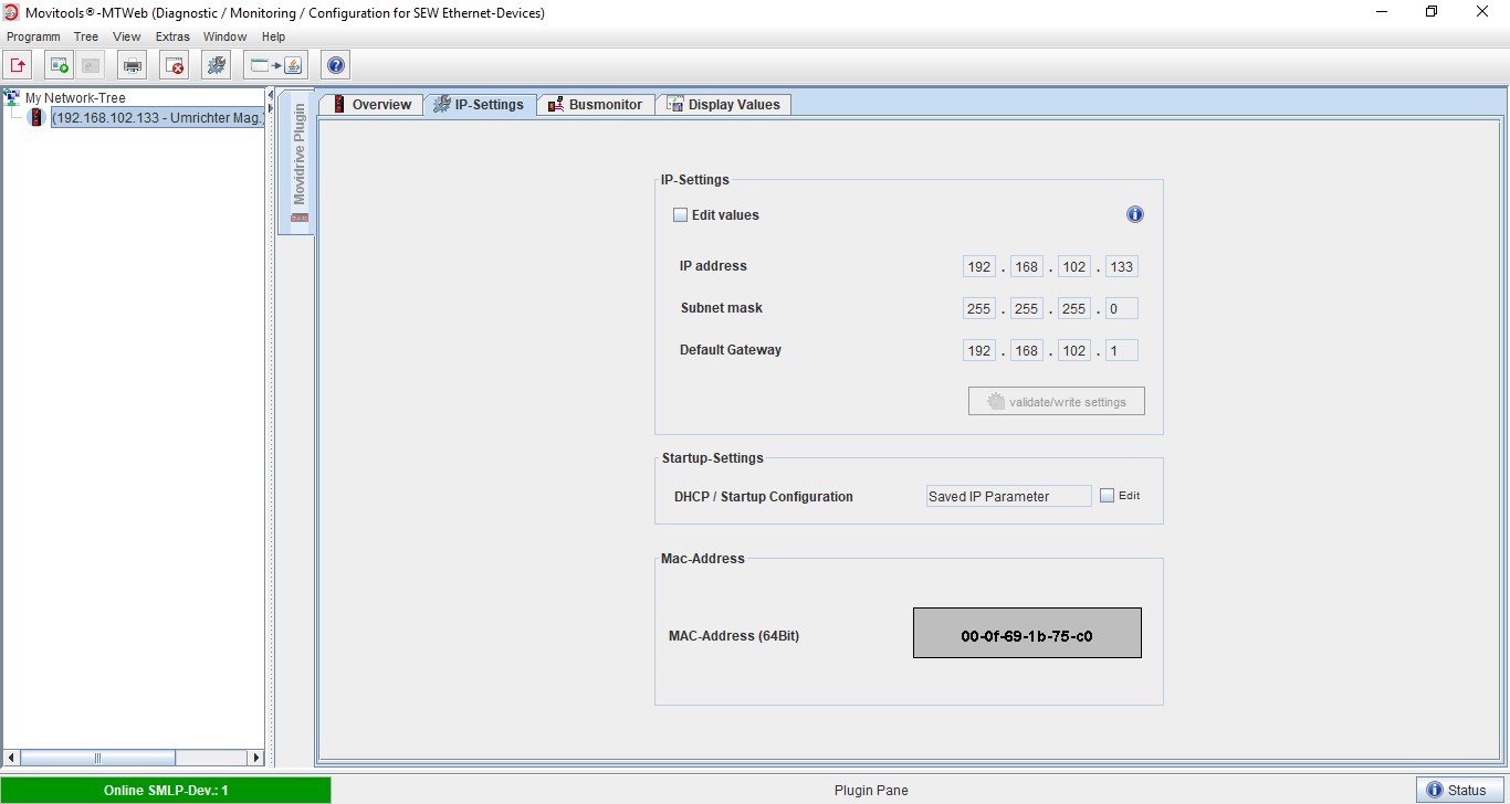
Today the
parameterization of the new inverter was on the program for me, so far it was only serially accessible via a cable from SEW via the USB port of my laptops. The inverter should be equipped with an IP address that allows it
to communicate with the Phoenix controller. Here I had to fight first with some problems, the inverter had
to be connected via LAN cable to the laptop.
By reading in a PDF (manual DFE33b), I knew the standard IP address of the inverter and set the configuration on my laptop so that could reach into the inverter. I wanted to make the commissioning via the web server of the inverter. Which turned out to be difficult as my laptop restricted access to the drive.
After several attempts to change something in the browser settings, etc., I
found out. That in JAVA I would have to add the inverter with its IP as an exception.
After doing that, I finally got access to the
inverter and adapted the IP address to our system. Now I could remove the LAN cable, the
Connect the inverter to our system with a LAN cable and the inverter
via our WLAN network. The inclusion of the inverter in the
PC-Works configuration failed.


04.12.2017
After
contacting SEW, it turned out that we have the wrong network card in the inverter. An Ethernet card
is installed, but we need a Profinet card. Fortunately, Mr. Wohlfahrt of SEW was able
to bring us such a card today. Now I had to set the IP address on
the inverter again, but this was much faster than the week before, because now I knew how it works!
After configuring the IP address, my colleague Fabian
was also able to record the inverter into the PC-Worx configuration without any problems. Now the
commissioning of the inverter was on the plan for me.
Since we have a position sensor on the magazine, which after he had lost his zero point Stromlos and a reference run needs I have a reference switch attached (initially only
provisionally). I found out with which setting in the parameters of the
inverter its reference.
In addition, I have temporarily connected two limit
switches on the inverter and successfully tested. Now the giver had to be told how
much distance he covers with one turn. I measured that and put it in the parameters of the
inverter.


11.12.2017
Today we tried to do the table positioning via fieldbus configuration. In cooperation with Fabian I have written table values into the inverter, which are to be approached by the PLC depending on the control. Initially, this did not work as soon as the inverter was told to go to position + 400mm, the engine started to turn, but not to the set 400, but in minus direction. After checking all parameters of the inverter and the subsequent unsuccessful attempts to reposition it via PLC, I found something out. In manual mode, the simulation wheel turned clockwise in reverse direction of the arrow and in reverse, it turned wrong. Then I turned in the Motor supply two phases together and the arrows in manual mode turned around right now!
Now we started another try of the Positioning via fieldbus and behold, the engine turned in the desired direction and drove in the direction of the 400. Then a problem started again, the engine turned up to about 420mm and turned back in the other direction to about 380mm, the repeats itself constantly and after several attempts by u.a. change the driving speed we broke off the attempt. I decided to restart the inverter by commissioning.
18.12.2017
Today, I first put the inverter back into operation. This time I chose the operating mode "Positioning with IPOS" during commissioning. Here it was possible to set the starting ramps of the
inverter, in other words, the program suggested different values to those in the inverter.
Now we start a new attempt of positioning, this time it worked much better! The engine still fluctuated a bit at the target position, but it was negligible.
I now drove all six positions of the magazine and noted the values to define them in the table positioning. In addition, I defined a basic position.
With Fabian we sent now the commands to the inverter the positions 1-6, in each case from basic position to drive. Positions 1-3 worked smoothly, at position 4-6 the inverter jumped out and
brought the error "following error". At first I was a little unbelieving, because the engine had not moved a millimeter. Since this had to be a speed monitoring problem, I decided to completely
deactivate the speed monitor in parameter 500.
The renewed attempt to drive 4-6 positions now worked without problems.
We tried now each an automatic expiry of the magazine when selecting Pizza + Tarte on the HMI. It worked as desired.
In my company, I was able to make two end plates for the HW limit switches. This I attached to the magazine today with screws. I also screwed the HW limit switches to the cover of the magazine.
15.01.2018
Today I set to continue the robot program. I taught the positions that I already had and recreated the program to the output station.
At the positions to put the sheet in the oven, problems came to light. The beverage gripper could not go far enough into the oven due to its curvature.
As a group, we decided to install the beverage station in a different location. This has the advantage that we can use the old grapple and could now go further into the oven.
Furthermore, we still create videos with our cell phones, since we for
had to submit another video to the Xplore contest.
22.01.2018
I have continued with the programming of the robot. The positions from the output station to the storage position of the sheet were still missing. After I had created all positions, the program was now obviously finished. Now I test my program in manual mode. Here were some positions out, which I had to pay a little attention. Furthermore, I helped with Fabian, Tobias during the installation of the dough band. In addition, the technical discussions with our project supervisors were on the agenda for our group.
29.01.2018
Today I read again in the manual of the robot how to activate the automatic operation of the robot. After I had activated the automatic mode I was able to carry out a first test in automatic with
sheet metal. The positions fit, I just put out some positions because they seemed unnecessary to me. I also adapted the traversing speed.
Now there were still tests in the automatic with pizza / tarte flambée. Here are still some problems crystallized out. Among other things, the document stations had to be moved because the pads
were not centered on the product. The biggest problem was the transition from dough sheet to the covering tape. The sheet was not always handed over in the same position, which meant that it was
in a different place each time it was attempted. This problem we solved with a "stopper cylinder".